In this project, I wanted to create modular, organic sound objects powered by the sun. The objects would breathe with the brightness of the sun, and have a subtle and complex envelope: I was tired of the typical clanging heard by wind chimes. At the time I began thinking of this project, I was studying some 19th century organ pipes that I was using in the Mocean project. I wanted to be able to hang these objects from trees and lightposts, like hanging fruit or icicles. The title of the project comes from the late fourteenth century, in a passage by the theorist Arnulf of St. Ghislain.
During my research, I ran across some interesting historical precedent for such a project. Along with the Utrecht Psalter, one of the best-known manuscripts among musicians, the Stuttgart Psalter from c. 820-830 illustrates various organs and other instruments. Probably made in a northern French scriptorium (St. Germain-des-Pres), the manuscript illustrates Psalm 136/137 ("By the rivers of Babylon...") with little organs hanging from trees. It is not known if this came from the artist's imagination, but there may be some connection with the pan-pipes sometimes shown hanging in foliage in pagan Roman sculpture. They are often shown like this in Greek psalters. The organs have seven pipes each, six or seven little key-tabs below the pipes, a frame, and an oblique bar across the pipe rows. These organetti could be fantasy, a miniaturization conjectured by the artist from larger organs, or he could have been famliar with Greek psalters in which such a motif was conventional. Since conventions were being fixed, later representations become, if anything, less actual, until perhaps the later thirteenth century (i).
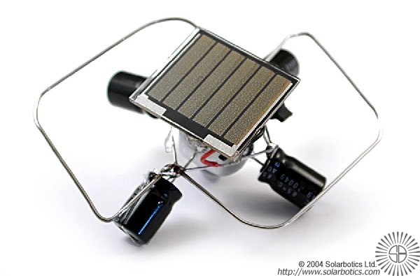
My exploration of the use of solar powered circuits began with a Symet Freeform 1381 Solar Engine kit from Solar Robotics. It uses a 1381 voltage detector the triggers at about two volts, letting charge flow from a capacitor into the circuit. I got this circuit to work, and experimented with various configurations of capacitors. I also experimented with another voltage-triggered engine from Solar Robotics, the Symet Flashing-LED Solarengine. Unfortunately, I found this engine to be less reliable, since when the flashing LED is exposed to light, it locked up and the circuit would not work. In both cases, an SC2422 solar cell and 1000uF capacitors were used. To move a blower motor, I was going to need a more powerful solar cell/capacitor/voltage detection set up. The 1381's only go up to approximately 4.4V; the blower I wanted to use was 12V/0.2A@10 cubic feet per minute.
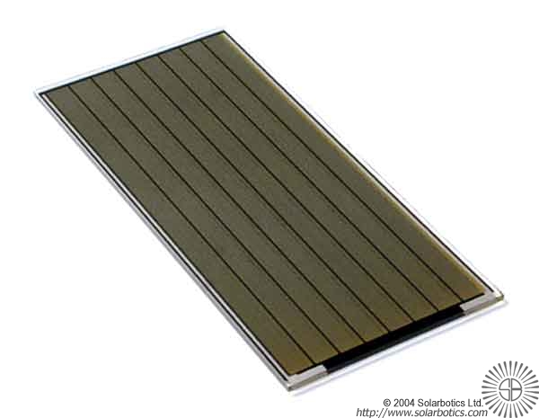
For a more powerful circuit, I experimented with the Maxim 8212 voltage monitor, and IC that has programmable hysteresis and trigger values (up to 16.5V). I connected three SC3782 (37mmx82mm) in series to achieve approximately 16V; the maximum current is ~40mA. To match the solar cells I connected three 1.0F, 5.5VDC Panasonic NF series double layer capacitors from Digikey, in series again.
To decide which resistors to use to determine the trigger voltage and the threshold voltage of the 8212, I consulted the PM3 Power Module manual from the Solarbotics Bicore Experimenter's PCB documentation. The PM3 is a solarengine that uses a set voltage drop before turning off, unlike the Miller Solarengine of the 1381, which uses a timer to determine when to shut off. I used a 3906 PNP transistor to drive the motor, since the positive side of the circuit is the side that is toggled, rather than the Miller Solar Engine, which toggles the ground line.
Unfortunately, it was rather difficult to configure the chip. The charts of resistor values in the Solarbotics documentation did not go up to the voltage I needed, so I tried calculating the voltage. I started with small values, and got the circuit working, but not smoothly. There is a descrepancy between the Solarbotics documentation and the Maxim documentation, with respect to the calculation of the resistor between the hysteresis and threshold pins. The Maxim documentation seems to work well. To test this, I tied a potentiometer into the circuit to test values.
The next step is to figure out how to get the circuit to recharge after it has discharged, and to find the right blower for the different pipes. The maximum amperage is 130mA@14.5V. This moved my current blower well. The blower movement lasts for about 45s, and the blower stops as the current drops to about 45mA. My current set up has the hysteresis resistor between 32K-76kOhm depending on the potentiometer setting, the hysteresis/threshold resistor at 22kOhm, and 10kOhm between the threshold pin and ground. With a bench power supply, I determined that at 12V and 100mA, I could get a small organ pipe to produce sound. Obviously, there is a lot of refinement left to be done!
i.) Peter Williams, The King of Instruments (London, 1993).